CNC shield is quite useful for stepper motor driving. Here, I demonstrated how to use simple arduino code to drive stepper motor with DRV8825.
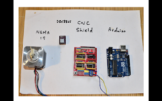
First, just simply mount CNC shield onto Arduino Uno.
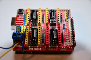
Make sure the direction of the shield was right, where both the USB port and power supply wire was on your left hand site.
The blue wire is my power supply which can be connect to 12-36V of power source.
Next step you can mount the DRV8825 chip onto the CNC shield. Make sure the DRV8825 chip goes like this direction. If you put the chip in the wrong direction, you will probably damage it.
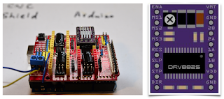
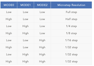
By adjusting the jumber underneath the DRV8825 chip, motors can be driven with different kind of microstepping mode.
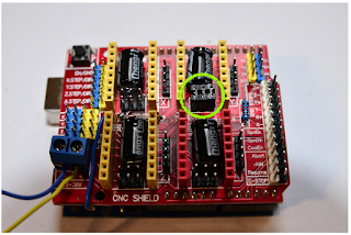
I put three number here so it means that I set it into 1/32 step driving mode. Which is the most precise one of DRV8825.
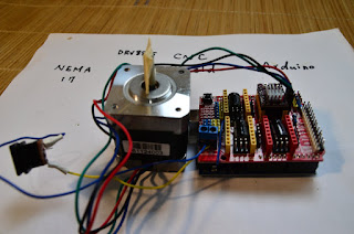
The motor can connect to the right site of the DRV8825.
Plug in the usb to your computer and upload these coded which will generate steps moving in both direction sequentially.
And you can started to see the stepper motor moving in both directions.
Have a look of this video :-)

First, just simply mount CNC shield onto Arduino Uno.

Make sure the direction of the shield was right, where both the USB port and power supply wire was on your left hand site.
The blue wire is my power supply which can be connect to 12-36V of power source.
Next step you can mount the DRV8825 chip onto the CNC shield. Make sure the DRV8825 chip goes like this direction. If you put the chip in the wrong direction, you will probably damage it.

By adjusting the jumber underneath the DRV8825 chip, motors can be driven with different kind of microstepping mode.

I put three number here so it means that I set it into 1/32 step driving mode. Which is the most precise one of DRV8825.

The motor can connect to the right site of the DRV8825.

Plug in the usb to your computer and upload these coded which will generate steps moving in both direction sequentially.
#define EN        8

//Direction pin
#define X_DIR     5
#define Y_DIR     6
#define Z_DIR     7

//Step pin
#define X_STP     2
#define Y_STP     3
#define Z_STP     4


//DRV8825
int delayTime=30; //Delay between each pause (uS)
int stps=6400;// Steps to move


void step(boolean dir, byte dirPin, byte stepperPin, int steps)

{

  digitalWrite(dirPin, dir);

  delay(100);

  for (int i = 0; i < steps; i++) {

    digitalWrite(stepperPin, HIGH);

    delayMicroseconds(delayTime);

    digitalWrite(stepperPin, LOW);

    delayMicroseconds(delayTime);

  }

}

void setup(){

  pinMode(X_DIR, OUTPUT); pinMode(X_STP, OUTPUT);

  pinMode(Y_DIR, OUTPUT); pinMode(Y_STP, OUTPUT);

  pinMode(Z_DIR, OUTPUT); pinMode(Z_STP, OUTPUT);

  pinMode(EN, OUTPUT);

  digitalWrite(EN, LOW);

}

void loop(){

  step(false, X_DIR, X_STP, stps); //X, Clockwise
  step(false, Y_DIR, Y_STP, stps); //Y, Clockwise
  step(false, Z_DIR, Z_STP, stps); //Z, Clockwise

  delay(100);

  step(true, X_DIR, X_STP, stps); //X, Counterclockwise
  step(true, Y_DIR, Y_STP, stps); //Y, Counterclockwise
  step(true, Z_DIR, Z_STP, stps); //X, Counterclockwise

  delay(100);

}
And you can started to see the stepper motor moving in both directions.
Have a look of this video :-)
Comments
Post a Comment